Performance Comparison of Data Conventors
AD-DA convertors are widely used in communication systems. Due to reliable operation of these devices accuracy and resolution tests are either provided by suppliers or users test it before use. Accuracy of these devices can be measured in many ways but basically can be determined by testing them with each other. Multimeters ,oscilloscopes or IC circuits will show output of DAC as well cause those devices have internal ADC at all. While testing those devices possible errors occur which are called Offset, Gain and Linearity errors and will cause loss at output codes. So as we are testing devices , we will try to reduce those errors as well.
This experience will cover performance tests and error interpretation between Arduino MKR WIFI 1010 , PMOD DAC-ADC , R2R DAC circuit. Now we will try to test the one has less bit resolution with the higher resolution device to see capability. Basically device under test is the one with less capacity. For each device tested with ramp , and different periods of sine signal and DNL,INL,FFT and Histogram analyze results will be discussed. Possible improvement solutions will be investigated as well.
Main purpose in here to experience this testing method with own built circuit R2R DAC and with the product which is industry built. So there should be higher losses on ENOB but the fact is this is home built converter and help us understand main basics of converter circuit.
Before start kindly apologize from you that I did not share theoretical part of the ADC , DAC convertors in here since this is a main subject. This article is an experiment you would be bit familiar to the analog to digital convertors and its basics , errors. But for the unclear parts please drop me a mail then I can give explanation or offer you some literature to understand the subject better.
Conduction of Experiment
- Necessary connections for R2R circuit and PMOD devices on Arduino MKR WIFI 1010 were built and configurations will change based on the experiments and circuit diagrams has shared below for you to do it.
- All experiments will be conducted with processing latest script. ( DataConverterCharV2.ino)
- Prof. Joerg Vollrath’s Javascript read oscilloscope data tool , Javascript FFT tool and Microsoft Excel are used to create graphs and process data.
- Arduino and R2R performances will be compared for ramp and different frequency sine signals
Setting up Environment
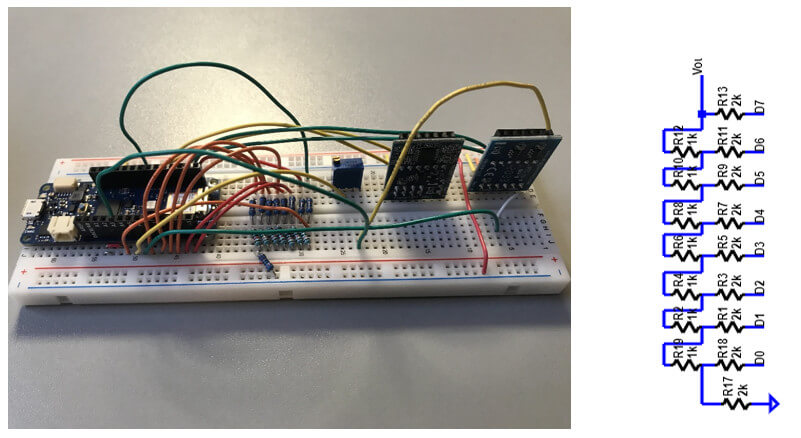
Picture above shows Arduino MKR WIFI 1010 board,PMOD AD2(left),PMOD DA2(right) on the board and established R2R circuit. DataConverterCharV2.ino is loaded inside the board and the frequency configuration is set by editing script. Following tests are going to be experienced ;
- Arduino DAC with PMOD ADC : Ramp test – INL , DNL / Sine test – INL , DNL , FFT , SNR with different frequencies.
- R2R DAC with PMOD ADC : Ramp test – INL , DNL / Sine test – INL , DNL , FFT , SNR with different frequencies.
- Arduino ADC with PMOD DAC : Ramp test – Histogram , INL , DNL / Sine test – INL , DNL , FFT , SNR with different frequencies.
Results will be compared and performance evaluation will be discussed in further sections. Arduino schematic can be seen below , the connections has done with reference of this. Because I did not have online oscilloscope , I extracted data from Arduino software tool and process it in Excel.
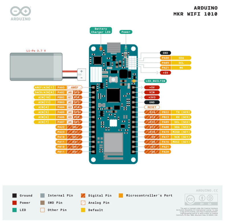
1. Arduino DAC – PMOD ADC
1.1 Ramp
Arduino 10 bits DAC was limited to 8 bits by script and PMOD ADC has 12 bits processing capacity. Therefore every code will occur 16 times (12-8=4 and 2^4 = 16 ). Ramp test results are stated below due to occurrences of same codes , just first quarter 4096 values are picked and analyzed.
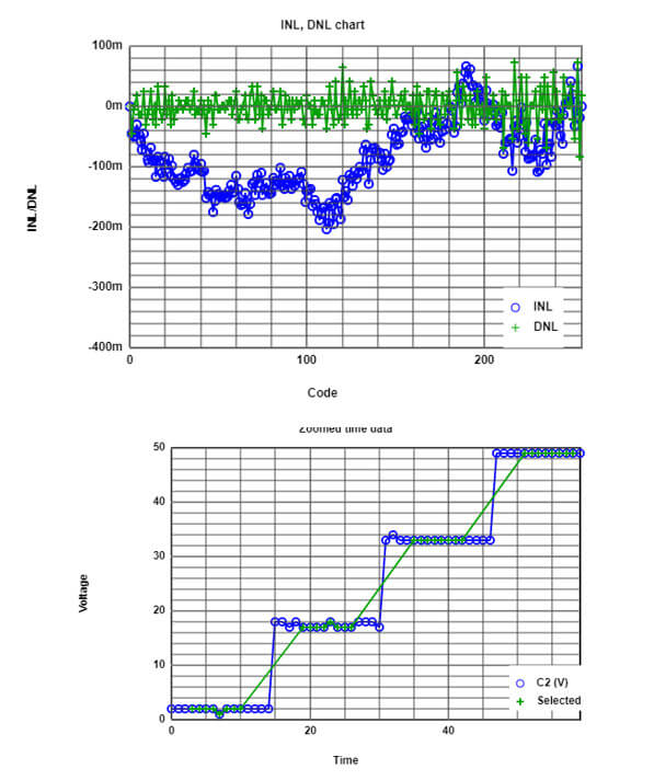
Averaging output length selected 8 to get more precise output which is marked with green circles in graph. INL max touched -200m which is less than half LSB and quite alright. In addition to it , we have Offset error = 1 and Gain error = 4075/4096. As we already aware of this errors , calibration can be done with correction output codes to measured reference point.
1.2 Sine – 1 Period
Here , we will look at the Arduino ADC performance with 1 period of sine signal and the aim is achieving maximum ENOB from 12 bits of output code.
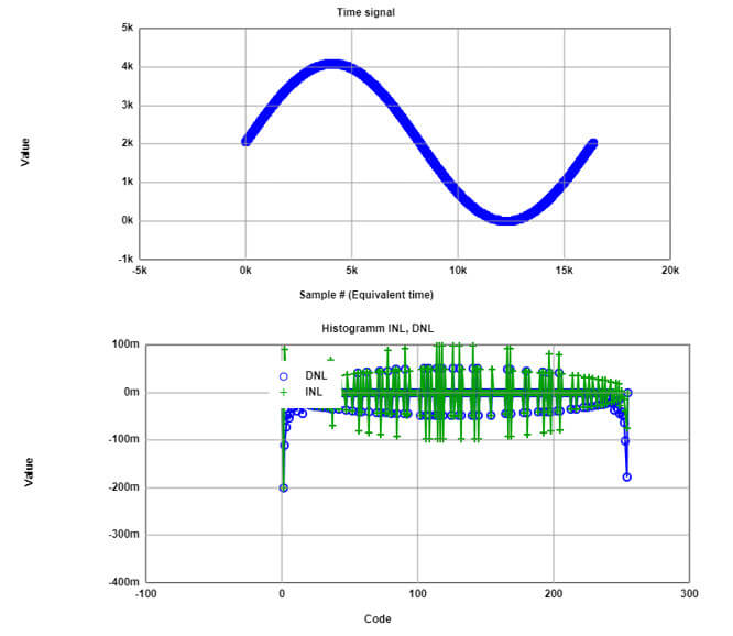
INLmax: 0.18 INLmin: -0.2 DNLmax: 0.36 DNLmin: -0.2 Missing Codes: 0
Minimum: 0 Maximum: 4076 Delta: 4076 Average: 2035.525390625
Frequency: 1
Signal magnitude dB: 60.19
Total noise magnitude dB:10.58
1-period of sine signal and 16k samples can be seen in FFT analyses above. INL and DNL values looks reasonable as well but had to sacrifice from 2 bits cause as it can be easily derived from SNR , our ENOB is 8.
Basically , we can say that from 12 bits of codes we can use only 8 codes with smallest linear errors. Gain error observed as 4076/4096 and Offset is 0.
[2] A cost-effective method of improving the resolution of the ADC is developing software to suitably process the converted analog-to-digital signal to achieve the same effect as a higher resolution ADC.
For example increasing sampling frequency can reduce power spectral density of component. Analog signals normally sampled a bit more than Nyquist frequency to avoid aliasing error. So if this signal can be sampled over more than Nyquist frequency with regarded methods , we can increase ENOB.
SNR overall_12 bits =SNR overall_8 bits ADC with oversampling
6.02 12 + 1.76 = 6.02 10 + 1.76 + 10*log(Fos/Fnqy)
The analog signal should be oversampled at a rate of 256 times more than the Nyquist rate to achieve the SNR of a 12-bit ADC with a 18-bit ADC.
1.3 Sine – 11 Period
Simply editing with script , we can obtain following graphs with FFT analyzing tool. The test with 10 number of bits came with 666 missing bits so with the help of ENOB calculation 8 bit of FFT results can be seen below.
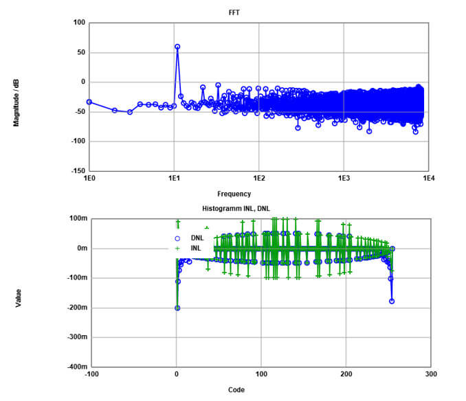
INLmax: 0.18 INLmin: -0.2 DNLmax: 0.36 DNLmin: -0.2 Missing Codes: 0
Minimum: 0 Maximum: 4075 Delta: 4075 Average: 2035.4517211914062
Frequency : 11
Signal magnitude dB : 60.19
Total noise magnitude dB :10.58
Frequency spectrum has peak at 11 with the same amplitude with 1-period of sine signal which is 60.19. Even as we can see INL DNL values mentioned above quite similar with the 1 period of signal.
This means basically our errors are same with all period as well. Even SNR outputs are exactly similar with 1 p. The only difference is Gain Error is 4075/4096 , it was 4076/4096 in 1 period of sine but its appear that it has quite small effect in LSB so we can not recognize even in INL-DNL graph.
2. R2R DAC – PMOD ADC
2.1 Ramp
This experiment will be conducted with R2R 8 Bits DAC which was built by myself. The output of R2R circuit is connected with PMOD ADC module and recorded results are processed with Microsoft Excel. Each code will be repeated 16 times due to resolution difference between ADC and DAC.
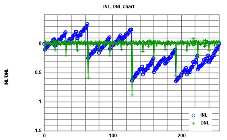
As it can be seen on the graph , INL-DNL performances is not less than 0.5 LSB. We can increase the average INL , DNL rate to get more precise results.
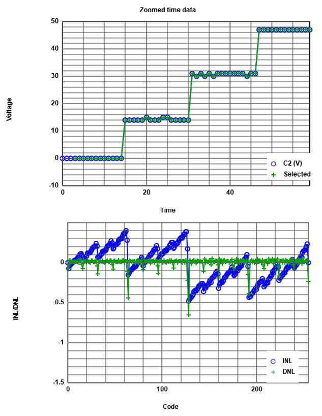
Now the updated results are above that as we assumed Max INL touched almost 0.65 LSB which was 0.9 LSB before. It looks increasing INL DNL average value help us a bit (green circles) but as it appear , it was the limit. Therefore to get more less LSB or get rid of possible connection failures , re-fixing the connection will be considered for the following sine tests.
Offset Error = 0 and Gain Error = 4080/4096 has calculated in Microsoft Excel for this R2R DAC test.
2.2 Sine – 11 Period
Same experiment repeated with 11 period of sine signal and FFT results are stated below.
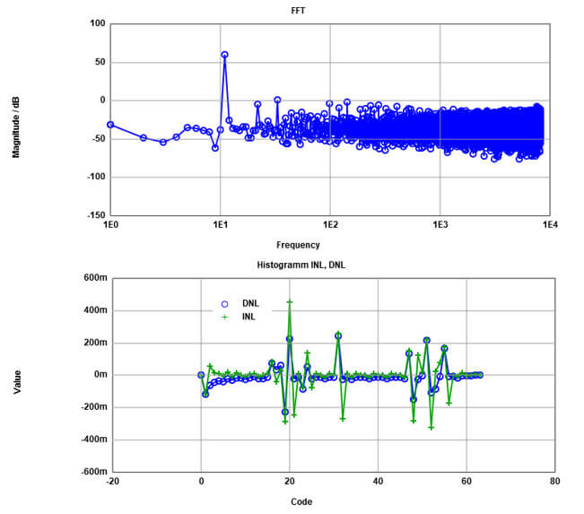
INLmax: 0.45 INLmin: -0.32 DNLmax: 0.24 DNLmin: -0.23 Missing Codes: 0
Minimum: 0 Maximum: 4080 Delta: 4080 Average: 2036.5108642578125
Frequency : 11
Signal magnitude dB : 60.19
Total noise magnitude dB :11.71
As it can be seen in frequency spectrum that we have our strongest component at 11 with the signal magnitude of 60.19. Total noise magnitude shows us we use 7.75 bits. To get less than 0.5 LSB INL-DNL error , we can see graph for 6 bits.
Gain error : 4080/4096
Offset Error : 0.
3. Performance Comparison between R2R DAC & ARDUİNO DAC
Performance analyses of both devices has already explained above with ramp , 1 period and 11 period of sine signals. It is quite appear that Arduino DAC gives better performances than R2R DAC. To get same performance we should sacrifice 1 or 2 more bit in R2R design which is actually not logical since we have max 8 bits over 12.
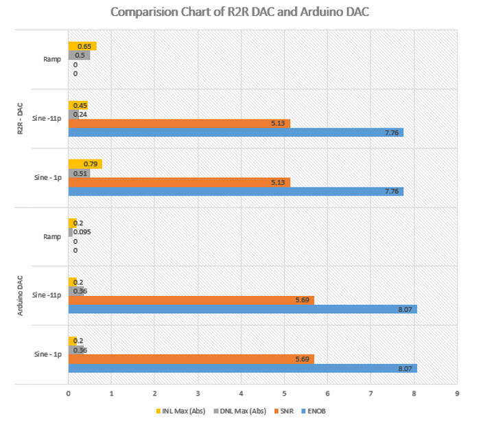
The chart shows numerical parameters of Arduino DAC and R2R DAC. Though ENOB shows 7.76 bits to remain with less linear errors , we can only obtain 6 at 11 period test. That is biggest gap between Arduino and R2R DACs. SNR is less in R2R cause noise magnitude is more bigger than Arduino so higher demodulator causes less rate.
INL DNL maximum absolute values indicated in charts and Arduino has really way better results than R2R. To reduce INL DNL for 1-p Sine R2R we can sacrifice from 1 more bits so it means from 12 we will use only 6 bits effectively and this is really ineffective.
Ramp signals seems better but linear errors are quite small in Arduino DAC compared to R2R.
Although R-2R ladder-based DACs and especially current-output ladders can inherently operate as high-speed current dividers [3], they are not able to meet the linearity and resolution requirements. and Al techniques [4] or dynamically calibrated current sources [5] are mainly employed to provide high performance, in terms of linearity and high resolution, but at the cost of slow conversion speed. On the other hand, high conversion speed with high performance can be achieved using either thermometer code DACs [6], at the expense of area and power dissipation, or laser-trimmed R-2R ladder-based DACs, using expensive manufactory procedures [7].Another compensating method includes hybrid DACs [8] or self-calibrated R-2R ladders.
4. ARDUİNO ADC – PMOD DAC
This section we will test Arduino ADC with look up table scripted to 8 bit with 12 bits PMOD DAC. Conducted experience covers ramp test and sine test with different periods and different pins of Arduino. Histogram test for ramp and INL , DNL analyses will show the deviation of ideal ramp and code occurrences.
Normally each code should repeat equally, otherwise the deviation will give us linearity errors. For the sine ; FFT , SNR , ENOB , INL and DNL errors should be interpreted.
4.1 Ramp
Today manufacturers of data converters frequently use the histogram method to verify the integral (INL) and differential (DNL) non-linearity specifications of their data converters. This approach, also referred to as code density test, is performed in the amplitude-domain of a data converter. During a histogram test a repetitive, signal with is applied to the analog-to-digital converter (ADC), generating a corresponding distribution of digital codes at the output of the converter. Any deviation from the output code distribution results in various errors that may be estimated with the histogram method. These error parameters covers DNL and INL.
Following graphs show ramp test INL DNL and histogram distributions for 2 different Arduino ADC pins.
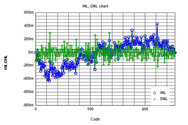
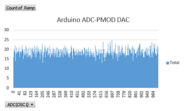
Gain error : 1018/1024
Offset Error : 0.
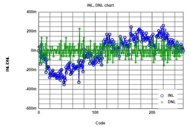
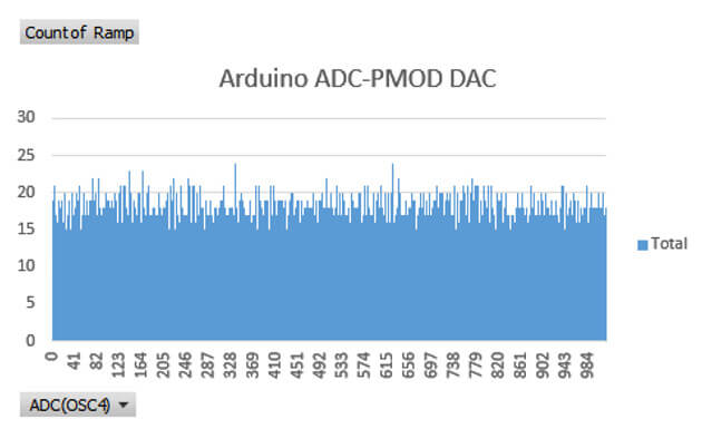
Gain error : 1019/1024
Offset Error : 0.
Both results are under half LSB but OSC1 has more oscillation in histogram so it caused more varied DNL and INL distribution but still inside the limits. Learned lesson is even though its in same board and same type of ADC , different ADCs give varying results so even we know the specifications of our ADC it is recommended to test it before using.
4.2 Sine – 11 Period
11 period of sine signal is tested by 2 times with different pins of Arduino (OSC1 and OSC4). Due to pin structure , sometimes deviation inside the code or the gain and offset errors will occurs. It cause different INL-DNL results. Regarded FFT and results are stated below.
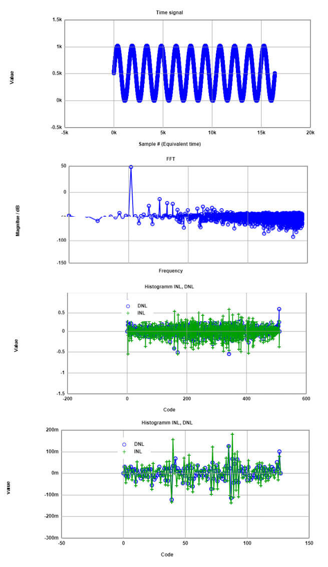
INLmax: 0.79 INLmin: -0.55 DNLmax: 0.79 DNLmin: -1 Missing Codes: 0
Minimum: 0 Maximum: 1019 Delta: 1019 Average: 508.95355224609375
INLmax: 0.18 INLmin: -0.14 DNLmax: 0.13 DNLmin: -0.15 Missing Codes: 0
Minimum: 0 Maximum: 1019 Delta: 1019 Average: 508.95355224609375
Frequency : 11
Signal magnitude dB : 48.11
Total noise magnitude dB :-7.16
First and second picture shows our 11 period and also there is some white noises can be seen in frequency graph cause their magnitudes are not that small to neglect. If we look at the our ENOB with the simple calculation 8.8 bits over 12 is the final value. This is quite alright and 1st INL-DNL graph is for 9 effective bits. It almost catch the 0.5 LSB values but around the latest codes, there is INL which is around 0.79. If it works for regarded application , 9 bits can be obtained from 12.
Second INL graph shows desired linearity errors less than 0.5 LSB with reduced bits to 7. Linear errors can be corrected with calibration and improved 9 bits option might work for regarded purposes.
Gain error = 1019/1024
Offset error = 0
4.3 Sine – 101 Period
Arduino ADC performance test conducted again with 101 period of sine wave and results are indicated below.
Following first 2 graphs shows Arduino ADC OSC1 performance for this experiment ENOB is calculated as 8.72 and as it can be seen below the graphs there are no missing bits. Due to increased frequency INL and DNL is pretty good for 9 bits.
To observe the best zero missing bits case , INL and DNL with reduced bits is not indicated but with 7 ENOBs quite good output can be achievable. If this case is alright for user can be used with gain of 2 bits.
Gain error = 1019/1024
Offset error = 0
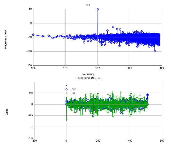
INLmax: 0.8 INLmin: -0.68 DNLmax: 0.8 DNLmin: -1 Missing Codes: 0 Minimum: 0 Maximum: 1019 Delta: 1019 Average: 509.02569580078125
Frequency : 101
Signal magnitude dB : 48.11
Total noise magnitude dB :-6.15
This case test repeated with ADC OSC4 and results are quite similar with ENOB= 8.75. This was reflected to INL and DNL but can not be easily seen. In here , 2 bits are sacrificed due to get desired linear errors. Results are quite good for users that need less linear errors.
Gain error = 1018/1024
Offset error = 0
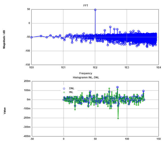
INLmax: 0.12 INLmin: -0.2 DNLmax: 0.14 DNLmin: -0.14 Missing Codes: 0
Minimum: 0 Maximum: 1019 Delta: 1019 Average: 508.96783447265625
Frequency : 101
Signal magnitude dB : 48.11
Total noise magnitude dB :-6.35
Interpretation of Results
In experiement combination of provided ADCs and DACs are tested successfully by each other due to resolution differences and results are shared above. As you can see there are some deviances occurred but this is the purpose of testing isn’t it ?
Tests showed that Arduino DAC is giving more better results than R2R DAC in terms of linear errors and ENOBs. The repeated experiments indicate that R2R DAC has always a bit less resolution than Arduino DAC. It is totally reasonable cause R2R is the circuit built in home with resistors and board so for better application we can get more precise results. Its quite open for failures and parasitic effects. But the biggest advantage is easy to set up and cheaper solution.
Gain and Offset errors shall be calculated during manufacturing of devices and a trimmable amplifiers are used for correcting these errors.
Stability of Arduino board is better than R2R cause for different periods of sine Arduino has given almost same results. Arduino ADCs are also give good results with PMOD DAC also we have seen that even they are same in structural view , different ADCs given different results with ramp and sine signal.
The occurrence test for ADCs is quite popular and shows distribution of codes and deviation can be calculated as well. ADC sine signals can be analyzed with Histogram test as well and obtained curve will called ‘Bath Tube’.
Sine tests give almost 8.8 ENOB and can be improvable up to 9 with less linear errors. In the other hand SNR was higher in comparison with ADC than DAC tests. There is another open discussion left that even though ENOB calculation and FFT tool shows zero bit loss , INL – DNL still more than 0.5 LSB so probably this error comes from the Java simulation tool and I already report it to the creator.
As a last words of me the method which we used to test DAC and ADC each other with the sake of different resolutions is quite related with industry therefore I hope that you found something fruitful in this article for you.
References
[1] Prof. Dr. Joerg Vollrath – Interface Electronics
[2] Jayanth Murthy MadapuraMicrochip Technology Inc. Achieving Higher ADC Resolution Using Oversampling “http://ww1.microchip.com/downloads/en/AppNotes/01152A.pdf“
[3] T. Shui, R. Schreier and F. Hudson, “Mismatch shaping for a current mode multibit delta-sigma DAC,” IEEE J. Solid State Circuits, vol.34, Mar. 1999.
[4] M. P. Tiilikainen, “A 14-bit 1.8-V 20-mW 1-mm2 CMOS DAC,” IEEE J. Solid State Circuits, vol. 36, Jul. 2001.
[5]. J. Bastos, A. M. Marques, M. Steyaert and W. Sansen, “A 12-bit intrinsic accuracy high-speed CMOS DAC,” IEEE J. Solid State , Circuits, vol. 33, Dec. 1998.
[6] “R/2R ladder networks,” Application Note AFD006, International Resistive Company, Inc., 1998.
[7] Y. Cong and R. L. Geiger, “A 1.5 V 14-bit lOOms/s self-calibrated DAC,” IEEE J. Solid State Circuits, vol. 38, Dec. 2003
[8] M. P. Kennedy, “On the robustness of R-2R ladder DAC’s,” IEEE Trans. Circuits & Syst. II, vol. 47, Feb. 2000.

